
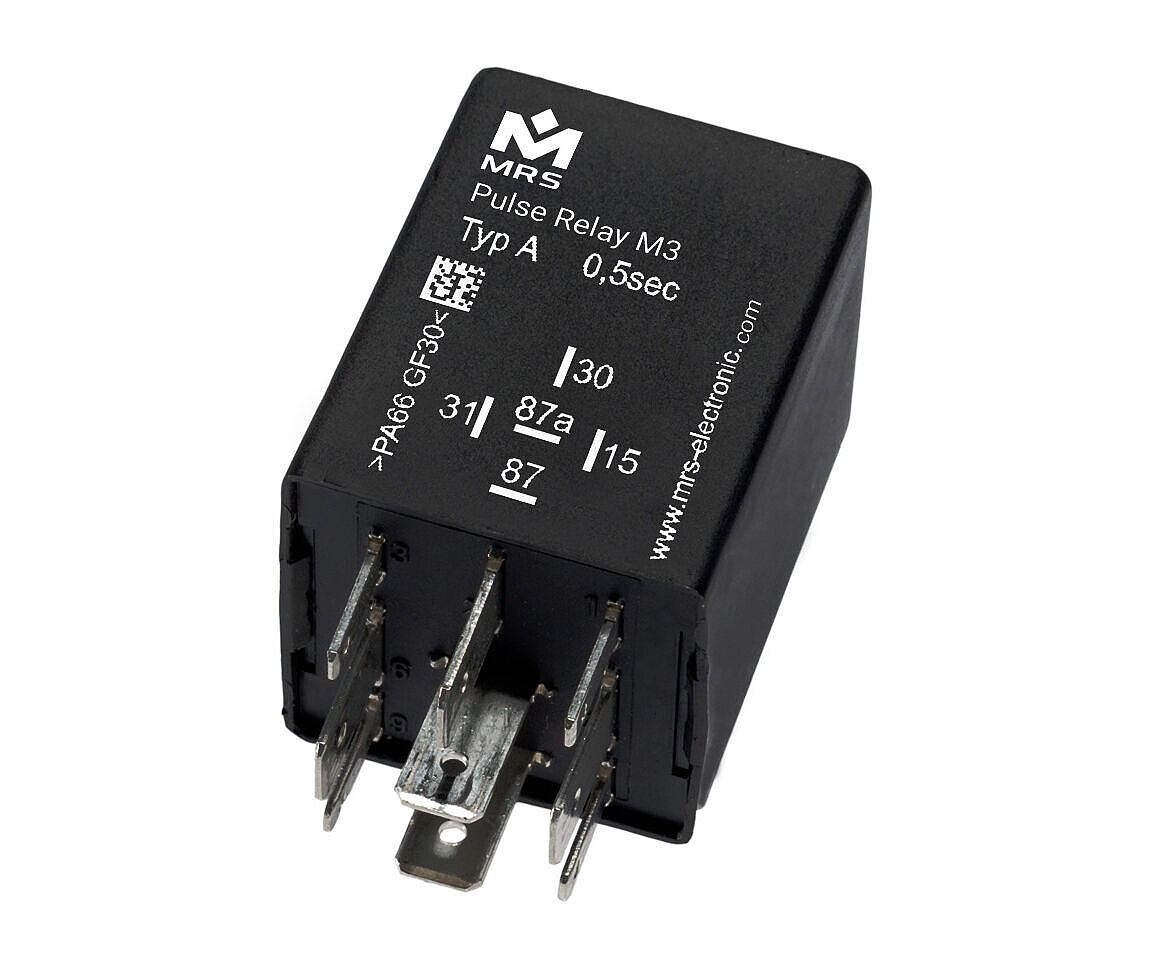
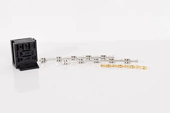
Pulse Relay M3 24 V
go to order options (100229x)
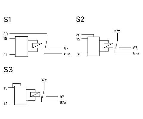
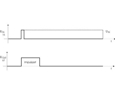
M3 impulse relays are used when loads are to be switched on or off for a defined period of time. When ordering, please indicate the desired pulse times. Circuit diagram S1 and S2: Operating voltage is applied to terminal 30. If voltage is applied to terminal 15, the relay picks up immediately for the specified time and then drops out again. The duration of the control signal has no influence on the output pulse duration (i.e. the relay cannot be retriggered).
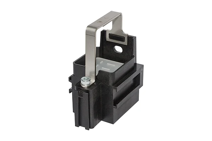
Circuit diagram S3: Operating voltage is applied to terminal 87z. If voltage is applied to terminal 15, the relay picks up immediately for the specified time and then drops out again. Circuit diagram S2 and S3: The contacts are separated from the control and can therefore be used in links. In this variant, the relay contact is completely potential-free and is therefore able to switch AC voltage. Housing shapes can be found in the Housing and basic body chapter.
Downloads


Technical details
Inputs and Outputs
| Number of pins | 5 |
|---|---|
| In-/Outputs (total) | 2 |
| Inputs (total) | 1 |
| Inputs (digital) | 1 |
| Outputs (total) | 1 |
| Relay outputs | 1 |
| Switching current | NC 15 A / NO 15 A |
Mechanical Properties
| IP rating | IP6K8 |
|---|---|
| Housing material | PA66GF30 |
| Dimensions | 30 × 30 × 40 mm |
| Switching cycles | 100000 |
Programming
| Programming software | MRS Realizer |
|---|
General
| Temperature range | -40 to +85°C |
|---|---|
| Operating voltage | 14-32 V |
| Current consumption | 2 ± 1 mA |
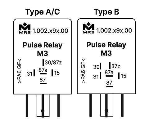
Markings
Order options
| Order no. | Name |
|---|---|
| 1.002.291.xx (1002291xx) |
Individual pulse time, Type A, Connection S1
|
| 1.002.292.xx (1002292xx) |
Individual pulse time, Type B, Connection S2
|
| 1.002.293.xx (1002293xx) |
Individual pulse time, Type C, Connection S3
|

Contact
Would you like to learn more or are you looking for a specific product?
Then please feel free to contact us.