
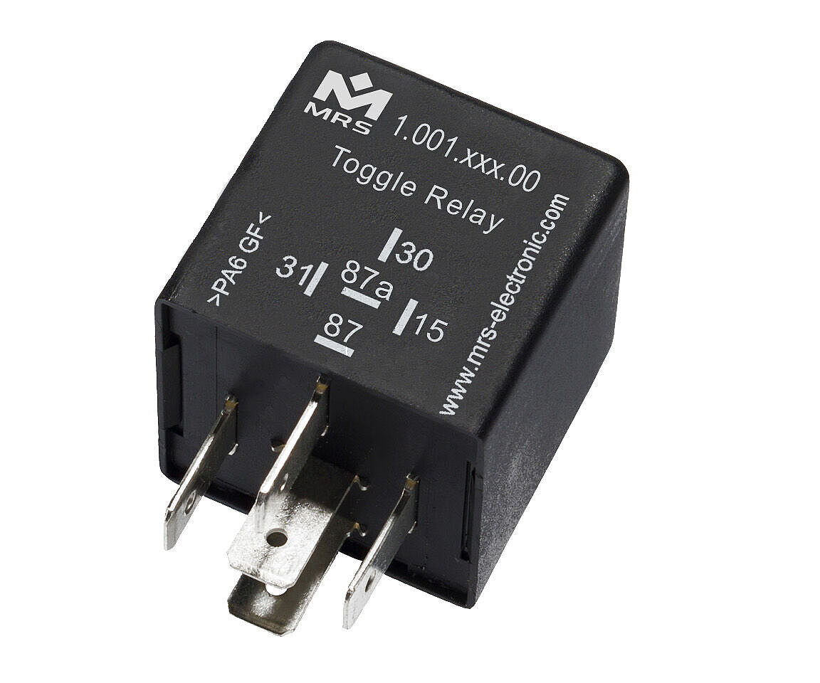
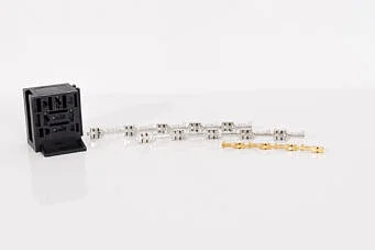
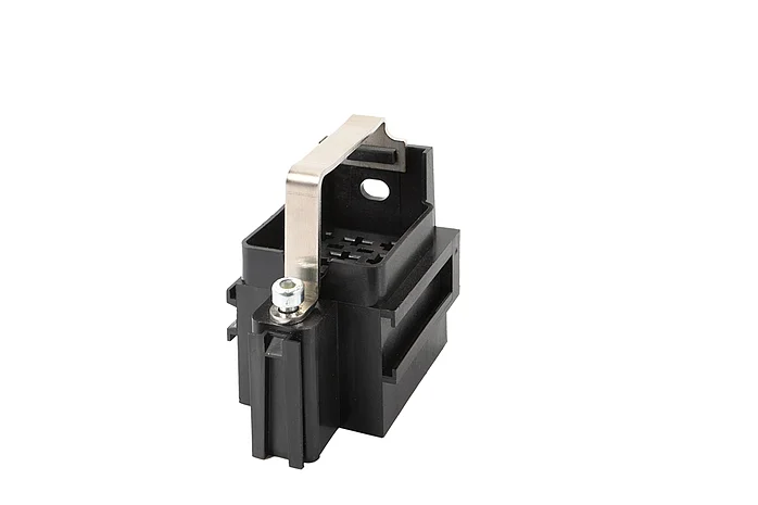
Toggle Relay M1 Compact 12 V
go to order options (100118x00)
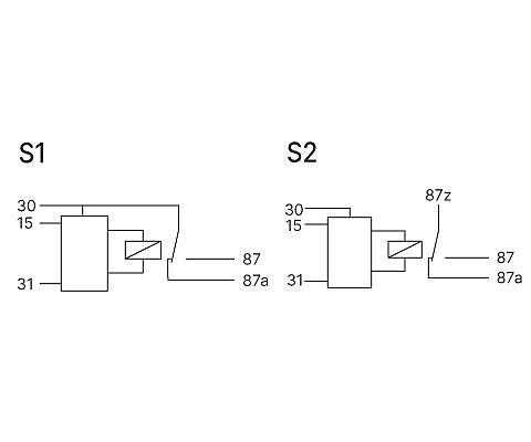
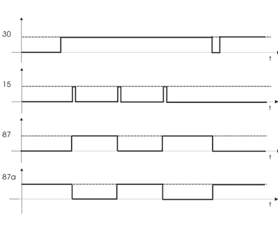
The area of application of the compact stepping switch relay is the switching on and off of consumers via push-button operation. Circuit diagram S1: With the compact stepping switch relay, a load can be switched via a button. If a positive / negative pulse is applied to terminal 15, the relay switches and holds itself. Another pulse switches again. (Latch switch or toggle flip-flop). Terminal 15 is debounced.
Circuit diagram S2: The contacts are separated from the control and can therefore be used in links. In this variant, the relay contact is completely potential-free and is therefore able to switch AC voltage. Housing shapes can be found in the Housing and basic body chapter.
Downloads


Technical details
Inputs and Outputs
| Number of pins | 5 |
|---|---|
| In-/Outputs (total) | 2 |
| Inputs (total) | 1 |
| Inputs (digital) | 1 |
| Outputs (total) | 1 |
| Relay outputs | 1 |
| Switching current | 20 A |
Mechanical Properties
| IP rating | IP53 |
|---|---|
| Housing material | PA66GF30 |
| Dimensions | 30 × 30 × 30 mm |
| Switching cycles | 100000 |
Programming
| Programming software | MRS Realizer |
|---|
General
| Temperature range | -40 to +85°C |
|---|---|
| Operating voltage | 9-16 V |
| Current consumption | 75 mA |
| Quiescent current (12V) | 1 mA |
Markings
Order options
| Order no. | Name |
|---|---|
| 1.001.181.00 (100118100) |
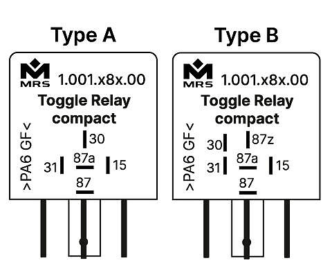
30A, Positive Edge Control, Type A, Connection S1
|
| 1.001.182.00 (100118200) |
30A, Negative Edge Control, Type A, Connection S1
|
| 1.001.183.00 (100118300) |
30A, Positive Edge Control, Type B, Connection S2
|
| 1.001.184.00 (100118400) |
30A, Negative Edge Control, Type B, Connection S1
|
Contact
Would you like to learn more or are you looking for a specific product?
Then please feel free to contact us.